5 Design Tips for Cast Molding with Thermoset Polyurethanes
Cast molding is one of the oldest and most common manufacturing processes that offers unmatched versatility, making it an excellent choice for product designers seeking flexibility and performance. When working with thermoset polyurethanes, you can achieve almost any shape, size, or form, tailoring your designs to meet specific needs.
To help you maximize your cast molding results, we've compiled five essential design tips that will guide you through the process, ensuring your products meet the highest standards of quality and performance.
Get Expert Guidance for Your Cast Molding Project! Complete our design tool to see how we can help bring your designs to life with our advanced solutions.
 1. Consider Wall Thickness
Like Reaction Injection Molding (RIM), cast molding allows for variations in wall thickness throughout a part. However, maintaining a uniform wall thickness is critical to allow liquid materials to set and solidify uniformly. Excessive variations in wall thickness and thin wall features may lead to air entrapment, tearing, or poor surface finishes. The recommended range of wall thickness should be at least .050” thick. Note, the larger the part, the larger the wall should be to ensure proper support. Gradual transitions between thick and thin walls are also recommended.2. Optimize Parting Lines
Parting lines occur where there are curves in the part. Excess material or flash on these lines can distort the overall shape and dimensions. The more complex or contours the shape features, the more parting lines will appear. To minimize parting lines, consider designing with straight profiles whenever possible. If complex contours are necessary, be prepared for secondary operations to deflash the parting lines by hand or machine the part to size to meet exact design specifications.
 3. Avoid Undercuts
Undercuts - sharp angles, cavities, or recessed areas misaligned with the mold's parting line - can create air traps, leading to bubbles or voids in the molded part. They also complicate the demolding process. To mitigate this, steer clear of undercuts whenever possible and incorporate fillet radii in your design to facilitate air escape and easier removal.
4. Size Matters
The size of the part will often determine the appropriate cast molding technique. Typically, small to medium size parts can be cast molded by hand, while large parts may require an automated process to prevent any weak spots such as bubbles, flow lines, or swirls, to name a few. To avoid these imperfections, the recommended solution is to discuss your project requirements early in the development stage with your polyurethane manufacturer to plan accordingly.

5. Know your Surface Finish
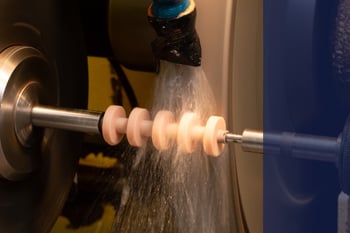
Cast molding can accommodate a variety of molded textures and surface finishes, usually dependent on the material. For instance, solids and most foams can mimic almost any molded texture or machined surface. Depending on the function of your product design, a machined surface may be ideal, particularly for foams, to unveil a different set of physical properties, such as Coefficient of Friction (COF). The part's function or application should drive the ideal material and surface finish.
By incorporating these five design tips, you can minimize potential defects in your cast molded parts. If you have questions about your product design, contact us here and let one of our polyurethane experts help bring your cast molded design to life!


